| ... | ... | @@ -2,7 +2,7 @@ |
|
|
|
---
|
|
|
|
Camera calibration is based on [OpenCV2 calibration](http://docs.opencv.org/2.4/doc/tutorials/calib3d/camera_calibration/camera_calibration.html).
|
|
|
|
|
|
|
|
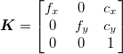
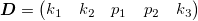
We are looking for the Camera Matrix **K** and Distortion Coefficients **D** described as:
|
|
|
|
The Camera Matrix **K** and Distortion Coefficients **D** writes:
|
|
|
|
|
|
|
|
 ,
|
|
|
|
 ,
|
| ... | ... | @@ -10,8 +10,11 @@ We are looking for the Camera Matrix **K** and Distortion Coefficients **D** des |
|
|
|
|
|
|
|
where  are camera focal lengths,  are optical centers, *p* and *k* are distortion coefficients.
|
|
|
|
|
|
|
|
### Calibration pattern
|
|
|
|
We chose classic black-white chessboard pattern with eight rows, seven columns and square's size approximately 35x35mm (Exact dimensions are specified in source code) as a calibration object.
|
|
|
|
## Calibration patterns
|
|
|
|
The chosen patterns are chessboard pattern and OpenCV3 ChAruCo pattern.
|
|
|
|
|
|
|
|
### Chessboard calibration pattern
|
|
|
|
The black-white chessboard pattern with eight rows, seven columns and square's size approximately 35x35mm is chosen as a calibration object.
|
|
|
|
|
|
|
|
### Calibration pictures
|
|
|
|
We must take pictures with calibration object in the camera's Field of View (FoV) in many different positions to cover most of the FoV. Moreover, we must respect that the whole chessboard must be visible.
|
| ... | ... | @@ -19,12 +22,11 @@ We must take pictures with calibration object in the camera's Field of View (FoV |
|
|
|
### Finding chessboards
|
|
|
|
We use OpenCV function `findChessboarCorners(gray,(rows,column),params=None)->ret,corners` for finding the chessboard in pictures, where `corners` are chessboard's internal corners in pixel (u,v) coordinates. After the chessboard is found, the position of corners is made more precise via OpenCV `cornerSubPixel(gray,corners,winSize,zeroZone,criteria)->None`, which finds them with sub-pixel precision. You can read more about this on the page listed above.
|
|
|
|
|
|
|
|
### Camera Matrix and Distortion Coefficients
|
|
|
|
When we know the position of chessboards in pictures (imagePoints) and correct size of squares and its positions (objectPoints), we can now estimate the Camera Matrix and Distortion Coefficients with OpenCV function `calibrateCamera(objectPoints,imagePoints,imageShape,None,None)->ret,cam_mtx,dist,rvect,tvect`, where `cam_mtx` is the wanted Camera Matrix and `dist` are Distortion coefficients.
|
|
|
|
|
|
|
|
### ChAruCo callibration pattern
|
|
|
|
|
|
|
|
The calibration using ChAruCo can be initialized using `CameraCalibrationLiveCharuco`. The parameters of a board must be specified inside the script. The package `Calibration.CharucoCameraCalibration` creates the board using `generate_charuco_board(dict, rows, columns, square length, marker length)`, where dict is an OpenCV3 AruCo dictionary, the rest is a shape of board and size of squares in meters.
|
|
|
|
|
|
|
|
The script opens a window with an image provided by a camera. Each time script spots a calibration pattern in the image, it saves the corners of pattern and moves on to the other image. After script collects corners from at least 10 pattern positions, you can press "q" for intrinsic camera parameters and distortion coefficients. The camera parameters are saved as YAML configuration file to a predefined directory.
|
|
|
|
|
|
|
|
|
|
|
\ No newline at end of file |
|
|
|
## Camera Matrix and Distortion Coefficients
|
|
|
|
When we know the position of chessboards in pictures (imagePoints) and correct size of squares and its positions (objectPoints), we can now estimate the Camera Matrix and Distortion Coefficients with OpenCV function `calibrateCamera(objectPoints,imagePoints,imageShape,None,None)->ret,cam_mtx,dist,rvect,tvect`, where `cam_mtx` is the wanted Camera Matrix and `dist` are Distortion coefficients. |
