|
|
|
# Rotation table
|
|
|
|
---
|
|
|
|
We use a rotation table connected to the MARS 8 unit for rotating an object.
|
|
|
|
The rotation table connected to the MARS 8 unit is used. We provided a python package, called `MarsTable`, which controls the MARS unit via USB (Setting and communication commands comes from [refence unit page](http://cmp.felk.cvut.cz/~pisa/mars8/mars8_man_cz.pdf), the documents are available in Czech only).
|
|
|
|
|
|
|
|
## Communication
|
|
|
|
The communication is done via USB and a serial communication module inside the unit (setting and communication commands can be found [there](http://cmp.felk.cvut.cz/~pisa/mars8/mars8_man_cz.pdf)). For easy communication with the unit there is a python package called MarsTable, which can perform all necessary operation for you.
|
|
|
|
|
|
|
|
## Table setting
|
|
|
|
The table setting is using an YAML file config as follows:
|
|
|
|
#### Table setting
|
|
|
|
The table setting uses YAML configuration files. The example follows:
|
|
|
|
```
|
|
|
|
---
|
|
|
|
regulator :
|
|
|
|
A:
|
|
|
|
P : 200
|
|
|
|
I : 0
|
|
|
|
D : 0
|
| ... | ... | @@ -17,64 +16,59 @@ regulator : |
|
|
|
```
|
|
|
|
---
|
|
|
|
|
|
|
|
## Finding the rotation axis of table
|
|
|
|
The rotation axis can be found when we put the calibration chessboard on the table and collect some images with different rotations. Thus, we can find transformations between these boards and camera and determine the rotation axis of table.
|
|
|
|
# Rotation axis of the table
|
|
|
|
The rotation axis of the table is obtained using the calibration pattern. The pattern is placed on the table. The picture of the table with the pattern is taken. The table performs a rotation in the right-handed direction without slipping the pattern. The second image of the table is grabbed.
|
|
|
|
|
|
|
|
We are looking for axis described as a direction vector  and a translation vector .
|
|
|
|
[//]: # ( The rotation axis can be found when we put the calibration chessboard on the table and collect some images with different rotations. Thus, we can find transformations between these boards and camera and determine the rotation axis of the table.) We are looking for axis described as a direction vector  and a translation vector . )
|
|
|
|
|
|
|
|
On following image we can see some basic relations between our coordinate systems. All we know are [R|t] transformations between camera coordinates and both board coordinates (green and red).
|
|
|
|
The basic relations between our coordinate systems are shown in the picture below. Only the transformations transformations [R|t] between camera coordinates and both board coordinates, green and red, are known.
|
|
|
|
|
|
|
|

|
|
|
|
|
|
|
|
### Finding transformation between boards
|
|
|
|
|
|
|
|
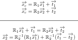
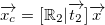
First, we have to find a transformation between both chessboards as:
|
|
|
|
First of all, the transformation between both chessboards positions must be found:
|
|
|
|
|
|
|
|
.
|
|
|
|
|
|
|
|
As you can see, we will work in the coordinate system of .
|
|
|
|
The coordinate system with the origin  is used.
|
|
|
|
|
|
|
|
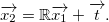
To simplify our equation we will use following identities:
|
|
|
|
Following identities are used to simplify the equations:
|
|
|
|
|
|
|
|

|
|
|
|
|
|
|
|
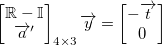
Thus, we end up with:
|
|
|
|
|
|
|
|
|
|
|
|
|
|
|
|
### Direction vector
|
|
|
|
|
|
|
|
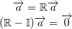
Next, we have to find the rotation vector . We know that, the vector parallel to rotation axis must satisfy:
|
|
|
|
The direction vectro  is parallel to the rotation plane and do not change its direction after rotation. Thus, it must satisfy following:
|
|
|
|
|
|
|
|
.
|
|
|
|
|
|
|
|
That mean the rotation vector is an eigenvector of the rotation matrix . Furthermore, the eigenvalues of  are complex conjugate numbers and one number . Thus, we use the eigenvector corresponding to  and call it the direction vector .
|
|
|
|
The rotation vector is an eigenvector of the rotation matrix . Furthermore, the eigenvalues of  are complex conjugate numbers and one real number . The eigenvector corresponding to  is used and called as the direction vector  (the vector must be normalized).
|
|
|
|
|
|
|
|
|
|
|
|
### Translation vector
|
|
|
|
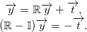
As you can see on the picture above when we translate vector  by the vector  and rotate it with the rotation matrix  we will end-up at same place. To simplify equation we call 
|
|
|
|
The translate vector  is transformed by the vector  and rotated it with the rotation matrix  it points to the same place as before. The transformation between these two positions is rigid, so it must satisfy following:
|
|
|
|
|
|
|
|

|
|
|
|
|
|
|
|
|
|
|
|
|
|
|
|
However, this equation have multiple solutions in a 3D space. So we must add an other condition to this to clarify the solution. We know that both origins are rotating in a plane with normal vector  from previous. Moreover, the normal vector must be perpendicular with the vector . We can add a following condition:
|
|
|
|
The equation has multiple solutions in a 3D space, resp. a circle of possible positions of the vector. Another condition must be added to clarify the solution. The direction vector  must be perpendicular to the translation vector  when the board coordinates are used. The following condition is added:
|
|
|
|
|
|
|
|

|
|
|
|
|
|
|
|
Now, we are able to write it as a matrix equation:
|
|
|
|
|
|
|
|
|
|
|
|
|
|
|
|
Previous equation is over-determined so we can't use casual inversion. Therefore, we use pseudo-inversion and receive the wanted solution.
|
|
|
|
|
|
|
|
### Translation and direction vector in camera
|
|
|
|
Previous equation is over-determined and cannot be inverted. The M-P pseudo-inversion is used.
|
|
|
|
|
|
|
|
To transform both the direction vector  and the translation vector , we use equation:
|
|
|
|
#### Translation and direction vector in camera
|
|
|
|
The direction vector  and translation vector  are in the coordinate system of the pattern. They must be transformed back to the camera system as:
|
|
|
|
|
|
|
|
,
|
|
|
|
|
|
|
|
where we replace  with  or .
|
|
|
|
|
|
|
|
|
|
|
|
## Rotating slice
|
|
|
|
|
|
|
|
We use the rotation about arbitrary axis described [here](https://sites.google.com/site/glennmurray/Home/rotation-matrices-and-formulas). |
|
|
\ No newline at end of file |
|
|
|
The rotation about arbitrary axis described [here](https://sites.google.com/site/glennmurray/Home/rotation-matrices-and-formulas) is used. |
|
|
\ No newline at end of file |
